Recent Results

Detection of chip formation with high speed camera

In order to understand the phenomena during different cutting processes accurately, in WP1 machine tool vibrations and chip formation are also investigated using High-Speed Camera. Based on the recordings the location of the shear layer and its angle can be detected using different image processing methods. Watch the videos below to observe the chip formation process for different cutting operations!

Finite element simulation of chip segmentation

The finite element simulation of the chip formation process is an extremely complicated task. The coupled simulation involves large strain analysis with temperature-dependent visco-plastic material behavior including material damage. Here, the chip segmentation phenomenon is modelled in the commercial finite element software ABAQUS.

Unsafe cutting zone

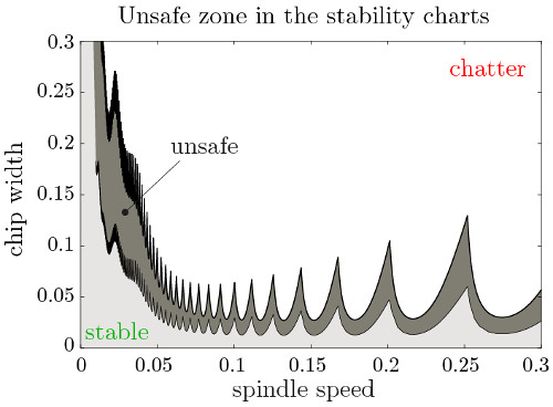
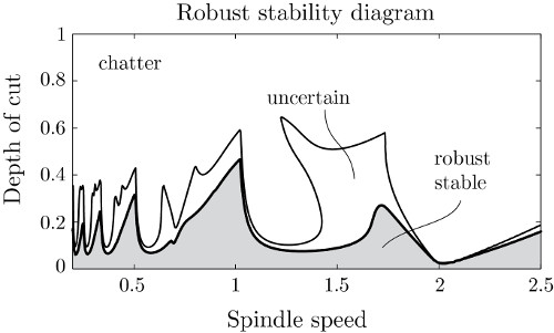
Experimental cutting tests often show different dynamic behavior from the one predicted by means of theoretical mechanical models. One reason behind this observation is the existence of nonlinearities in the machine tool-workpiece system. For instance, the cutting force is typically a nonlinear function of the chip thickness. Due to this nonlinearity, the stability lobe diagrams determined by standard linear stability analysis often fail to predict the region of chatter-free technological parameters. Namely, there exists an unsafe zone in the stability lobe diagrams of machining, where the cutting process is linearly stable, but machine tool chatter may still initiate for large enough disturbances like material inhomogeneity, holes in the workpiece material or external excitation. As a result of this research, we derived a simple analytical formula to estimate the unsafe parameter region. This way, the proper selection of the technological parameters used for machining becomes possible, which guarantees the avoidance of machine tool chatter caused by large disturbances.

Surface location error on beam-type workpiece

In milling processes, the intermittent cutting force may lead to harmful vibrations. These vibrations are classified into two groups. One of them is the self excited vibration which comes from the loss of stability due to the regeneration effect and these vibrations lead to unacceptable chatter marks. The other one is the forced vibration which can lead to high Surface Location Error (SLE) in case of resonant spindle speeds. The dynamics of a beam-type workpiece is considered which is modelled by means of Finite Element Analysis (FEA). Both the forced vibration and the stability properties are predicted along the tool path. The surface properties are computed on the stable regions of the stability chart which presents the chatter-free (stable) parameter domain as a function of the spindle speed and the tool path. The theoretical results are compared to the measured SLE and surface roughness.

Chatter-free and CSLE-stable technological parameters for milling

In milling processes, the desired machined surface cannot be perfectly achieved even in case of chatter-free machining due to the thermally induced errors, the trajectory following errors and the most significant one: the cutting force induced vibration errors. In case of vibration, the error is represented by the so-called Surface Location Error (SLE), which is the distance between the machined and the required surface position. In case of roughing operations, these errors can have a significant impact on the surface position due to the interaction between the subsequent SLEs. The machined surface depends on the previously resulted SLE through the variation of the radial immersion. The variation of the SLE values is governed by a discrete map, which may lead to an unpredictable final surface position. The parameter range where this unpredictable final SLE occurs is presented together with the traditional stability chart representing the chatter-free domains of cutting parameters. With the proposed methods, the traditional stability chart can be improved, from which chatter-free and CSLE-stable technological parameters can be selected.

Cutting force determination for milling

During the simulation of the cutting processes, the accurate model of the cutting force must be determined. In WP1 different methods are used to determine the cutting force. One of them is based on the measured force during the milling operations. During the measurement the x-y-z component of the cutting force is measured accurately by a Kistler dynamometer and the angular position of the tool is determined by an optical sensors. The method is based on the transformation of the instantaneous cutting force into the radial and tangential coordinate system which is plotted against the theoretical chip thickness. In this way the cutting force characteristic can be plotted directly and there is no need for intermediate steps in the fitting process.

Robust stability charts

Prediction of machine tool chatter requires the characterization of the dynamics of the machine-tool-workpiece system and the cutting force characteristics. Due to imperfect measurements, noise, uncertain and varying operational conditions, the mathematical models provide a deficient representation of the system. This leads to the need for the adaptation of robust stability analysis methods, which guarantee stability against bounded uncertainties and perturbations. The aim of this research is to analyze the sensitivity of the conventional stability lobe diagrams and to provide a reliable method which predicts the uncertain regions where machining operations may become unstable.